
Types of OPO’s

TYPES OF OPOs
This is the second in a series of Optical Parametric Oscillators. Read part 1 here.
SINGLY RESONANT OPO
An OPO is called singly resonant when reflective mirrors form an optical cavity around the crystal for either the signal or the idler beam. This is shown in Fig. 3 with the signal resonant. In this example, the input pump beam is shown in blue. The signal and idler are shown in green and red. The resonant signal is shown between the two mirrors as an area filled with green light. The output includes the generated signal and idler beams as well as some residual (unused) blue pump light. For illustration purposes only, Fig. 3 shows a prism separating the output beams.

Figure 3. Example of an optical parametric oscillator (OPO) in a linear configuration, as opposed to a ring configuration. An input pump beam, shown in blue, is transmitted by mirror 1 and enters the nonlinear crystal where it generates a signal beam, shown in green, and an idler beam, shown in red. Mirror 2 transmits the idler and is partially transmissive (partially reflective too) for the signal. Mirror 1 is a high reflector for the signal. When this OPO is operating, the signal beam circulates between the mirrors as shown in green. This OPO is singly resonant since only the signal is resonant between the mirrors. The output is the signal and idler plus some residual pump light.
DOUBLY RESONANT OPO
An OPO is called doubly resonant when both the signal and the idler are reflected and resonate in the cavity. In some cases, the pump may also be in a reflective cavity around the crystal. If the gain provided by the crystal for the signal or idler exceeds the losses in the cavity for that beam, then the OPO is said to be over threshold, and the OPO will do its job--it will produce coherent signal and idler light. Although doubly resonant OPOs have the advantage that they can work with lower pump powers, there are tight constraints on their cavity length which make building doubly resonant OPOs challenging. Singly resonant OPOs are much more common.
LASER PUMP BEAMS
OPOs can use a wide range of laser pump beams. The pump lasers can be continuous or pulsed. Pulsed pump lasers might have almost any pulse length, ranging from Q-switched lasers to mode-locked lasers. The OPO will generally produce output with a temporal profile similar to the pump laser. CW pumps drive CW OPOs; pulsed pumps drive pulsed OPOs. For a seminal text on lasers, including CW, Q-switched, and mode-locked lasers, see: Siegman, Anthony E., Lasers. University science books, 1986.
Long pulses, often from Q-switched lasers, are frequently used for pumps in higher power systems. Ultra-short pulses from mode-locked lasers can also be used to pump OPOs, in which case the resonant cavity around the nonlinear crystal is usually designed so the resonant light’s round-trip time equals the time between pump pulses. That way the resonant light and the pump light pulses are synchronized so they can overlap in time. Continuous wave (CW) pumps are used to generate continuous signal and idler beams. CW OPOs can give the most stable single wavelength (equivalently, single frequency) output. This is often advantageous for spectroscopy and sensing applications. OPOs can be tuned to scan or select the desired output wavelength. It is often most practical to change the phase matching to select a desired output wavelength by changing the crystal temperature.
In OPOs, the pump, signal and idler beans are often collinear. However, phase matching is also possible in some crystal arrangements when the beams are not all collinear. Properly configured noncollinear pump and signal beams can phase-match over a broad band of signal wavelengths. A broad band of wavelengths is necessary in order to have ultrashort pulses. Consequently, OPOs or OPAs for generating ultrashort pulses may use noncollinear phase matching.
LASER CAVITY DESIGNS
OPOs can use a wide range of laser cavity designs. Linear cavities, as shown in the example in Fig. 3, are simpler. However, ring cavities, such as the one depicted in Fig. 4, have light going in a loop-like path, and this has some advantages.
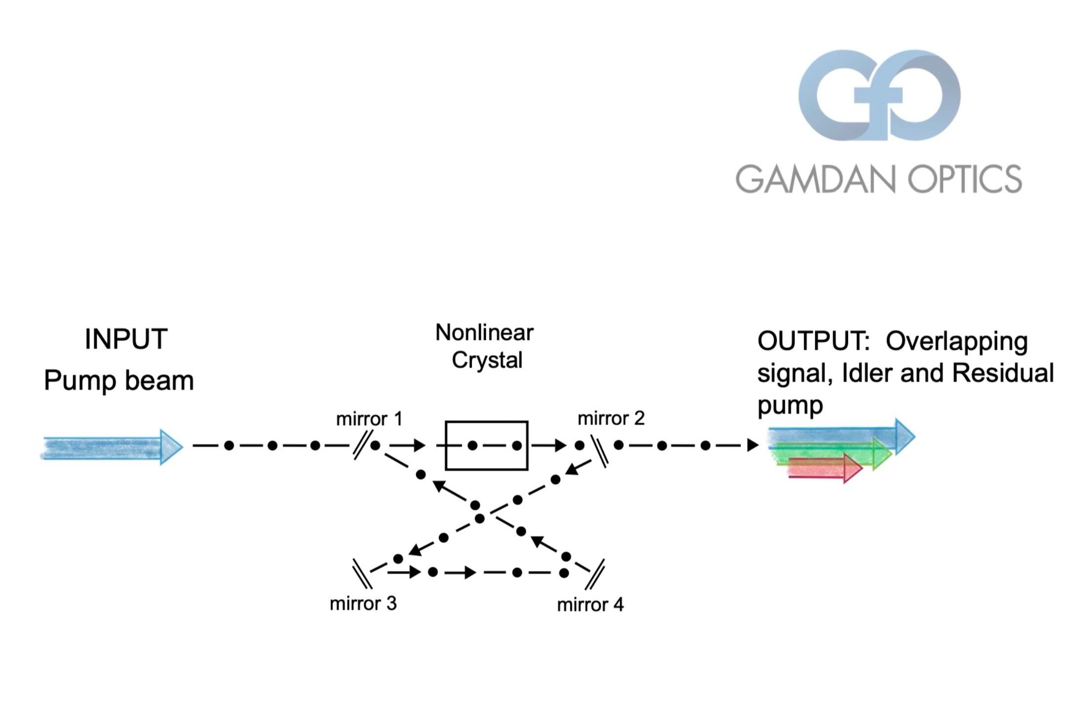
Figure 4. A ring resonator for an OPO in a “bow tie” configuration. In this example, only the signal is resonant. The signal is the green light. Mirror 1 transmits the pump. Mirror 2 transmits the idler and partially transmits the signal. Mirrors 3, 4, and 1 are high reflectors for the resonant signal. The output signal and idler beams, plus some residual pump beam light, all pass out through mirror 2 in this example. Many other design variations are possible.
In an OPO, the gain is only in one direction, unlike in most lasers. This makes it relatively easy to design a ring cavity for an OPO that has light circulating in only one direction. With some care, the ring cavity can avoid having any surfaces that reflect the pump beam back into the pump’s source. It is important to avoid any such reflective feedback to the pump which is destabilizing. It is hard to avoid feedback of pump light from a linear cavity. Optical isolators can attenuate some of the pump feedback, but isolators are never perfect, and they also add cost and complexity. That is why ring cavities are often used in OPOs.
Stay tuned and we will be looking next at Different Crystals for Different OPOs.
DR. WILLIAM GROSSMAN, AUTHOR
Will Grossman is a consultant retained by GAMDAN, and his role is to help our customers be more successful with nonlinear optics. His technical expertise includes laser design, nonlinear optics, and laser reliability. Dr. Grossman’s laser designs are used around the world in commercial products. More on the author can be found here.